
 The Coach Space
Your first cross-laminated timber (CLT) kickoff call can sound like code—wall panels, hold-downs, fire sealant—before you even unmute. CLT stacks lumber in alternating layers to form flat panels that replace walls, floors, and roofs, yet how those panels connect to everything else makes or breaks the job. The United States already tracks 2,833 mass-timber projects built, in design, or under construction as of June 2026, so your team will likely face CLT soon. This guide breaks down the core components and connections, then closes with five quick questions to help you sound like a pro.
Start with the CLT project as a system
A cross-laminated timber building is a prefabricated kit, with every piece cut to millimeter accuracy and numbered for the crane crew.
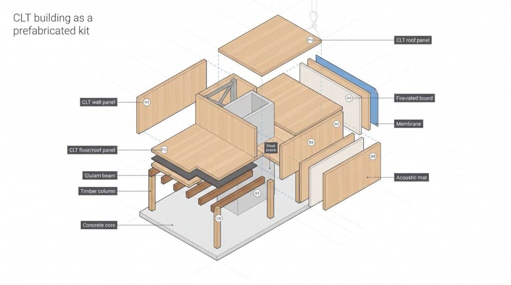
Panels do the heavy lifting. Factory sheets are typically 2–10 ft wide and up to 60 ft long, according to the APA – The Engineered Wood Association. Wall panels carry gravity loads and, where detailed, brace the building against wind or earthquakes. Floor and roof panels span between supports; a 3-ply (4 ⅛ in) panel covers up to about 12 ft, while 5- and 7-ply panels reach 14–21 ft (WoodWorks).
Beams and columns fill the gaps. Glulam (glue-laminated) or LVL (laminated-veneer lumber) beams bridge longer distances, and matching timber columns carry loads to the foundation.
Concrete and steel keep things honest. A concrete slab or core anchors the stack and limits lateral sway. Steel braces or knife plates can stiffen an atrium or hide inside timber joints when appearance matters.
Performance layers finish the shell. Fire-rated board, peel-and-stick membranes, and acoustic mats wrap the structure so the timber also meets code for fire, moisture, and sound.
With this kit in mind, the next section looks at what every connection must do to keep those components working together.
Understand what every connection has to do
Before you size screws, we need a shared dictionary:
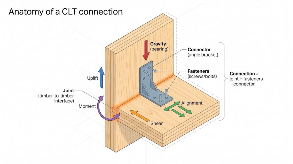
- Joint – the physical gap or interface between two pieces of material.
- Fastener – the screw, nail, bolt, dowel, or rod that bites into the timber.
- Connector – the bracket, plate, hanger, shoe, or concealed fitting that organizes those fasteners.
- Connection – the complete, load-bearing assembly of joint + fasteners + connector.
A single connection may need to:
- Carry gravity in bearing.
- Resist shear so panels don’t slide.
- Withstand uplift when wind tries to peel walls away.
- Hold alignment so floors stay flat.
- Transfer moment where rotation must be locked.
Once everyone speaks the same language, scan the available mass-timber connectors and fasteners, then cross-check capacities and installation notes against the independent WoodWorks Index of Mass Timber Connections (updated June 2024) to confirm that each detail suits your loads, fire rating, and sequencing plan.
Most catalog parts then fall into a few connection families that show up on nearly every project.
Self-tapping structural screws
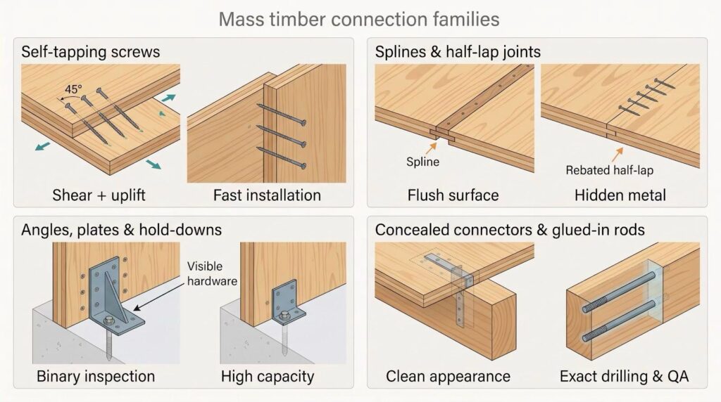
Fully threaded self-tapping screws—often 1/4 in. to 5/16 in. (6–8 mm) in diameter and up to 20 in. long—have become the workhorse of mass timber (WoodWorks).
- Angled installation clamps two panels together, delivering shear and tension strength in the same stroke.
- Straight installation through a half-lap acts like a hidden dowel, adding uplift resistance without an exposed bracket.
Because one screw can act as fastener, clamp, and mild reinforcement, designers specify them for everything from diaphragm splines to column splices. Capacity varies with diameter, length, embedment, and angle, so check each value against the 2024 NDS Chapter 12 and the manufacturer’s data.
Manufacturers publish the numbers you need. Simpson Strong-Tie, for example, groups its mass-timber structural screws, beam hangers, holdowns, angle brackets, and glued-in rod solutions in one place and offers a downloadable catalog of CLT connectors and fasteners with load tables and code reports, plus a CLT diaphragm design guide based on the 2021 SDPWS. Its tools range includes a Timber Drive tool for driving long structural screws while standing.
The WoodWorks Index of Mass Timber Connections lists 30-plus screw-based details, which shows their versatility.
Next up: splines and half-lap joints, the minimalist cousins that keep floor and roof panels perfectly flush.
Splines and half-lap joints
When two floor panels meet mid-span, the fastest way to make them act as one sheet is a spline connection. Crews slide a ½-inch-thick plywood or LVL strip into routed grooves along each panel edge and pin it with nails or #10 screws. The step takes minutes and leaves the ceiling face clean (WoodWorks).
A half-lap goes a step further: each panel has a shallow rebate (about ¾ in. deep) so the faces overlap. A row of 45-degree self-tapping screws threads through both layers, locking the joint and adding uplift resistance. CNC time is higher, but alignment is nearly perfect and the surface stays flush.
Both details hide metal inside the wood, shielding fasteners from direct fire exposure, but only if the joint is sealed. Apply the specified tape or intumescent sealant during installation so smoke, sound, and moisture can’t pass; treat that seal as part of the structural joint, not cosmetic cleanup.
Next up: angles, plates, and hold-downs, the visible workhorses that tie walls to floors and foundations.
Angles, plates, and hold-downs
Exposed steel angles or knife plates bolt a wall panel to the floor, seat a beam, or pin a rocking shear wall back to its footing. Because the geometry is visible, field inspection is binary: either the bracket bears tight or it does not.
Hold-downs provide the muscle for uplift. A heavy strap or concealed profile clamps the panel and hooks into a concrete anchor.
The price of that simplicity is visibility. Bare steel raises fire-protection demands, often calling for extra timber cover or an intumescent wrap, and it can show through acoustic ceilings. Many teams use heavy-duty brackets at the ground floor, where forces peak, and switch to concealed connectors on upper levels.
Hardware looks costly per piece, yet the clear shapes cut crane time: crews spot the bracket, swing the panel in, drop bolts, and move on. Saved minutes often offset the material premium and keep total installed cost competitive.
Next, we will meet the silent types: concealed hangers and glued-in rods that disappear inside the wood until inspection day.
Concealed connectors and glued-in rods
Sometimes a design needs strength that hides in plain sight. Concealed beam hangers drop into CNC-cut pockets; once the panel is seated, only timber grain shows. Two or three self-tapping screws or dowels pin the device, and the required pocket depth, screw angle, and edge distance come straight from the product’s ICC-ES or ETA report. No field improvisation is allowed.
Glued-in rods push invisibility further. High-strength steel bars bond deep inside pre-drilled holes with a two-part epoxy, creating stiff, ductile splices for point-supported floors and moment-resisting wall joints.
Inspection is critical. Rod depth, hole diameter, adhesive batch, curing temperature, and torque must match the evaluation report. Treat each rod like a post-tensioned tendon: verify, document, and sign off before the cavity closes.
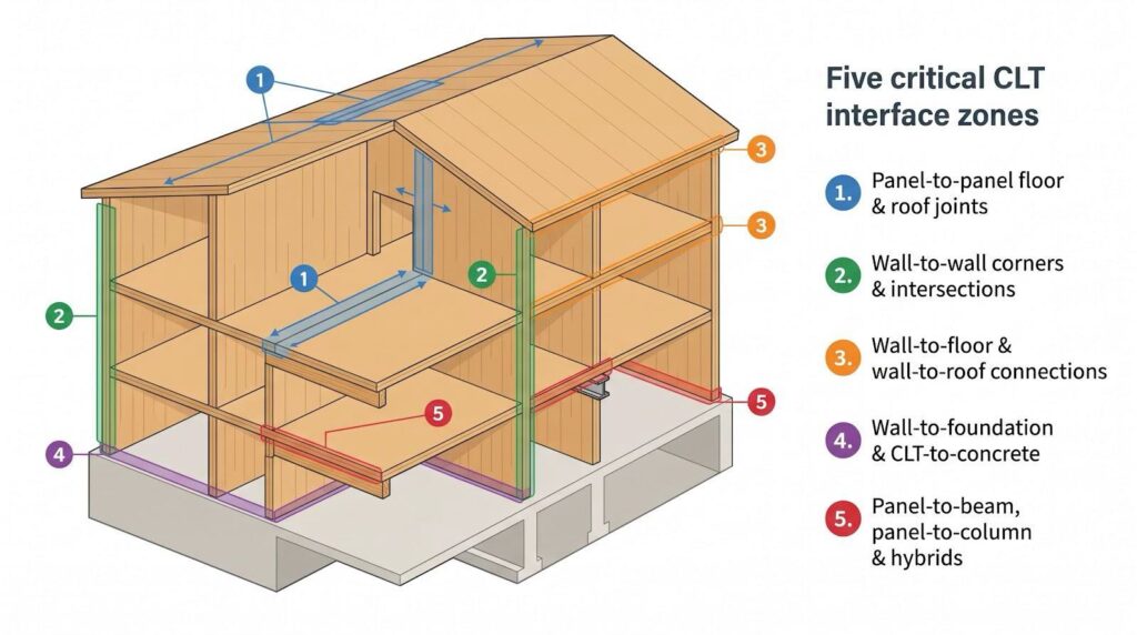
With the core connector families covered, the next section maps where they live: the five interface zones every CLT project must resolve.
1. Panel-to-panel floor and roof joints
Floors and roofs act as horizontal diaphragms, so panel seams must remain rigid. Typical solutions are:
- Spline or half-lap joints nailed or screwed at 6–12 in. on-center per WoodWorks CLT diaphragm guide
- Butt joints reinforced with 45-degree self-tapping screws for added uplift resistance
Alignment matters as much as strength. A spline sitting even 1⁄16 in. proud can show through the finished ceiling, and a gap wider than a credit card leaks sound, smoke, and fire. Crews dry-fit each seam, drive the pattern, then seal with approved tape or a compressible gasket before the crane moves on. When done right, the joint vanishes; the diaphragm behaves like a single sheet.
Next: wall-to-wall corners, where that same continuity must turn ninety degrees without showing movement.
2. Wall-to-wall corners and intersections
Vertical seams stack loads for multiple stories, so even small misalignments add up quickly. Crews plumb the first wall, bring the intersecting panel flush, and lock the joint with 6–8 mm (¼–⁵⁄₁₆-in.) self-tapping screws driven at opposing 45-degree angles every 300 mm (12 in.). This pattern, recommended in the WoodWorks wall-splice library, clamps the edges like a zipper and stops one panel from sliding as its neighbor shrinks or swells.
Corners follow the same rules, just at ninety degrees. A half-lap or concealed corner bracket fits inside the cavity, while a continuous bead of ASTM C920-listed fire-rated sealant closes the V-shaped gap. The sealant is structural in its own way: it blocks smoke, drafts, and sound while preserving the wall’s fire rating.
Because every future retrofit depends on these hidden choices, teams record screw size, angle, spacing, and sealant type before panels leave the factory. Years later the joint is invisible behind finish, but the load path keeps working.
Next stop: wall-to-floor and wall-to-roof connections, where your choice of platform versus balloon framing changes the entire erection rhythm.
3. Wall-to-floor and wall-to-roof connections
Your framing rhythm hinges on one decision: platform or balloon construction.
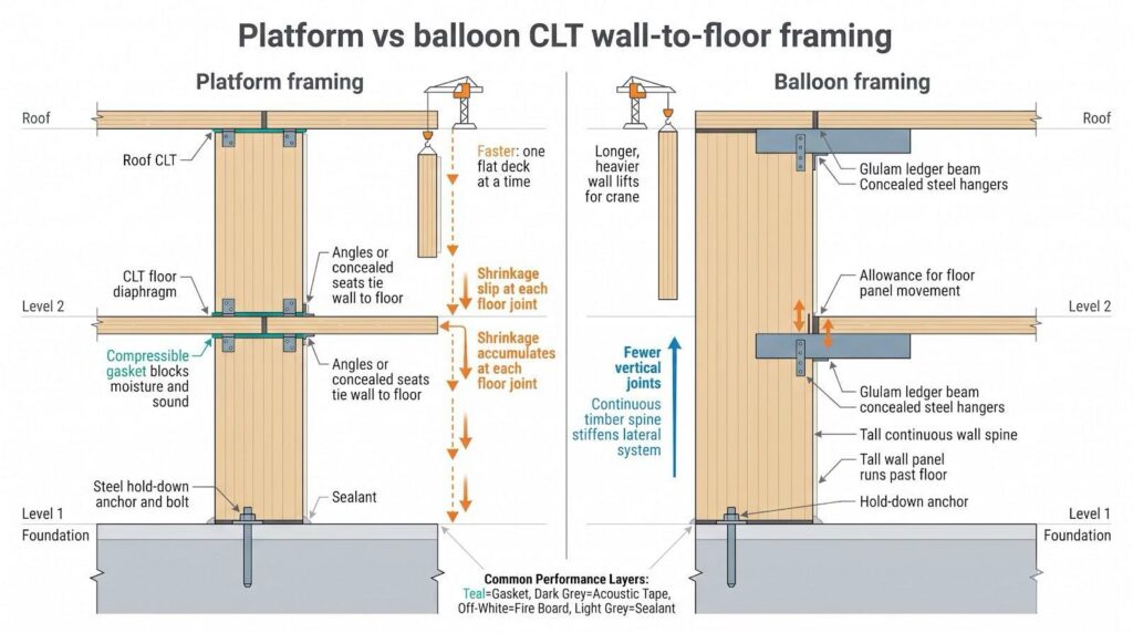
Platform framing finishes one level before the next walls rise. Each wall panel bears on the CLT floor diaphragm, usually on a 3–5 mm compressible gasket that blocks moisture and sound. Angles or concealed seats tie the wall to the panel edge, while hold-downs clamp the stack to the foundation. The payoff is speed—one flat deck at a time—but every floor joint adds slip the engineer must include in wind and seismic drift checks. WoodWorks estimates ≈1 in. of vertical shrinkage in an eight-story platform building with 5-ply floors if moisture drops eight percentage points.
Balloon framing runs tall wall panels past the floor, and the diaphragm hangs like a shelf from ledgers or hangers. The continuous timber column stiffens the lateral spine and reduces vertical joints, but cranes must handle longer, heavier walls, and ledgers need detailing to accommodate future panel movement.
Whichever path you choose, remember the hidden layers: fire-rated board on exposed steel, acoustic tape where timber meets timber, and a continuous bead of sealant that closes the hairline gap you will never see again after cladding. Screws and brackets make the structure stand; these quiet details make the building perform.
4. Wall-to-foundation and CLT-to-concrete interfaces
Concrete tolerances are measured in centimeters, while CNC-cut timber arrives within ±2 mm. Bridging that gap starts with a 3–5 mm compressible sill gasket or EPDM strip, which keeps moisture out of the end grain and lets crews nudge the first panel plumb before bolts lock home.
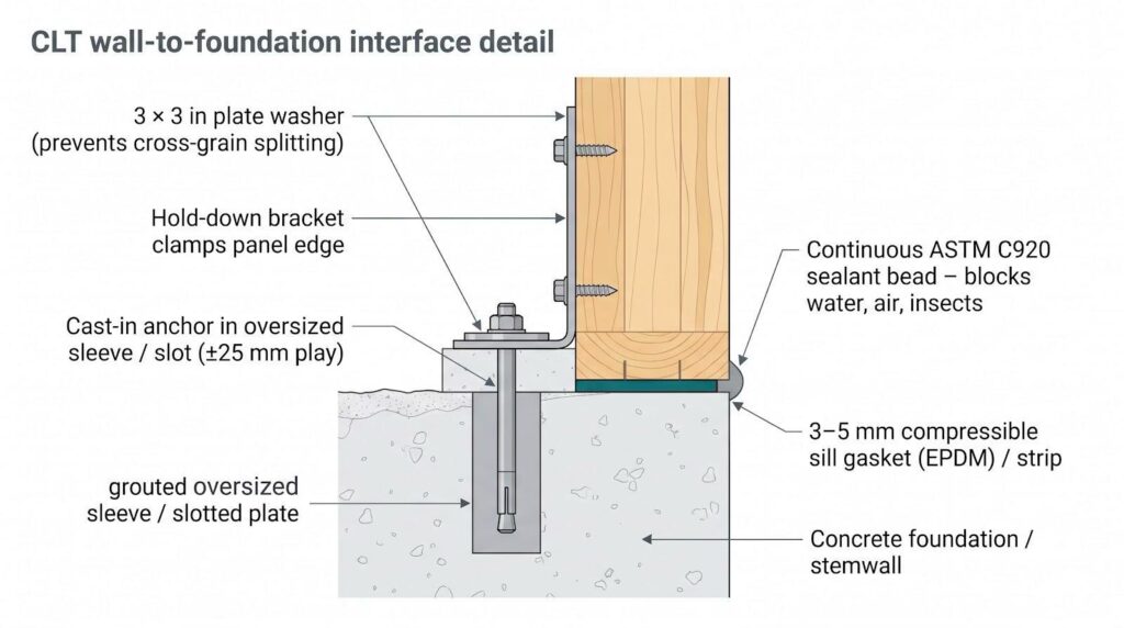
Cast-in anchors remain the preferred choice, but jobsite conditions rarely match the 3D model. Oversized sleeves or slotted plates provide ±25 mm (1 in.) of play and still deliver full capacity once grouted. When schedules force post-installed anchors, include the manufacturer’s full cure time, often 24 hours at 21 °C, so early tightening does not erode uplift resistance.
Hold-downs finish the load path. They clamp the panel edge, grab the anchor, and resist the suction that high winds or seismic overturning create. Engineers size them for both tension and shear, but only if the bracket sits flush; WoodWorks QA guidance notes that omitting the required 3 × 3-inch plate washers on anchor bolts can lead to cross-grain bending and splitting of the sill plate.
Sealant comes last but protects longest. A continuous ASTM C920 bead at the timber-concrete joint blocks water, air, and insects in one pass, which is inexpensive to install and costly to correct once finishes hide the evidence.
With the foundation locked, we can turn to the hybrid joints higher up: panel-to-beam, panel-to-column, and other timber-to-steel or timber-to-concrete interfaces.
5. Panel-to-beam, panel-to-column, and hybrid interfaces
Mass-timber buildings rarely stay pure. A steel girder may clear a ballroom span, or a concrete core may rise for elevators. Where materials mix, movement and fire set the rules.
Timber-to-steel. The simplest joint is bearing: a 6–10 mm steel seat plate bolts to the column, and the CLT panel lands on the ledge. If the joint must disappear, a concealed hanger can work, but only after the engineer checks char depth (per AWC FDS) and adds a 10–15 mm mineral-wool thermal break behind the plate.
Timber-to-concrete. Concrete creeps and shrinks, while timber swells and shrinks. A slotted knife plate or oversized bolt hole offering ±12 mm of slip lets the panel settle without prying the anchor loose. A 3 mm neoprene pad under the plate prevents hard spots and damps vibration, often avoiding hairline cracks in finishes.
Timber-to-timber. Wood bearing on wood is simpler. A panel can sit directly on a glulam beam or column with only a bead of acoustic sealant. When crews cannot drive screws from above, the shop routes a pocket for a concealed hanger that locks once the panel slides home.
Across all hybrids, keep anything that burns away from anything that conducts heat. Fire board, mineral-wool plugs, and 25 mm air gaps stop a steel plate from acting as a heat sink that chars timber faster than the code test assumes.
How teams choose between connection options
Selecting a connection is less about scrolling a catalog and more about answering six questions: loads and ductility, fire, moisture and movement, acoustics, fabrication, and inspection.
Load and ductility
First question: what forces will this joint see, and how should it behave when they arrive?
- Gravity – panel self-weight plus live loads such as people, furniture, and snow.
- Shear – in-plane forces that try to slide panels past one another.
- Uplift – suction from wind or seismic overturning that tries to peel panels off their seats.
- Moment – rotational forces at rigid corners or beam seats.
Engineers combine the worst case of these in design load combinations (see ASCE 7-22). The connection must carry the demand and still provide the right ductility, its ability to deform without sudden failure.
For life-safety seismic design, aim for connections that yield in a ductile way rather than splitting the timber; shallow-angle self-tapping screws often do this by yielding gradually. Knife plates with tight bolt holes may match static strength but can fracture suddenly, offering little warning.
A quick sense check: projects in high-seismic zones (e.g., S_D or S_E) need yielding hardware or fuse details. If the architect insists on razor-thin metal reveals, flag the conflict early; you can hide hardware or let it yield, but doing both rarely works.
Fire performance
Timber chars at about 0.65 mm/min under the standard furnace curve, creating an insulating layer. Steel loses strength rapidly above 600 °C, so any exposed plate or screw head becomes the weak link.
Think in three steps:
- Bury the metal. The AWC Fire Design Specification shows that 25 mm of wood cover can delay a steel screw’s critical temperature by 15 minutes in a 1-hour test.
- Seal every gap. A 2025 Fire Technology study found that unprotected 6 mm and 10 mm air spaces behind a concealed hanger raised internal temperatures; filling the gap with intumescent sealant limited the rise.
- Match the rated assembly. If the field installation changes screw length, spacing, or cover from the product’s ICC-ES report, the rating is void.
Get fire right and the structure buys critical minutes for sprinklers. Miss a detail and no char-rate model can save a melted hanger.
Moisture, corrosion, and dimensional movement
Timber swells about 0.25 percent across the grain for every 1 percent rise in moisture content. Steel ignores humidity until it rusts, while concrete wicks water. The joint must referee all three.
- Capillary break. A 3–5 mm EPDM sill gasket or stainless plate keeps CLT off damp concrete and permits minor adjustment.
- Exterior protection. Sloped metal flashing (≥ 1:12) sheds rain, and vapor-open WRB membranes let panels dry toward conditioned air.
- Fastener finish. Electro-galvanized screws fit conditioned interiors; coastal or pool zones need 304/316 stainless.
- Allowing slip. A 2.4 m-wide CLT floor can shrink ≈ 3 mm as EMC drops from 15 percent to 8 percent. Slotted holes, oversized washers, and compressible tapes absorb that movement so panels do not pry on rigid steel.
Acoustics and airtightness
Structure alone cannot stop noise or air.
- A 10 mm recycled-rubber mat under a floating floor improves impact insulation by + 12 IIC in WoodWorks lab tests.
- A continuous bead of ASTM C920 sealant at panel joints can cut air leakage by 70 percent (Oak Ridge 2024 study).
- Pre-cut boxes, grommets, and tapes keep door, window, and service penetrations tight; a 50 mm unsealed hole can add 0.1 ACH at 50 Pa.
Design the seal before the saw turns on, and the building will feel quiet, tight, and efficient from day one.
Fabrication and erection
Shop drawings must let the crane crew “build Lego.”
- CNC strategy. Two-sided machining adds ≈ \$4–\$6 per pocket yet makes concealed hangers possible.
- Tool access. If a screw head sits 150 mm inside a pocket, plan for a stub-driver bit; lost minutes become crane dollars (\$8–\$12/min typical).
- Sequence. Panels ship in erection order; a ten-minute drawing check often saves a 30-minute crane hold.
Inspection and documentation
IBC 2024 §1705.5 requires special inspection of mass-timber connections.
Inspectors focus on:
- Fastener type, diameter, and head style.
- Length, angle, and embedment (±2 mm, ±2° typical tolerance).
- Concealed connectors seated and photo documented before cover.
- Fire- and acoustic-sealant continuity checked at each lift.
- Product labels retained for lot traceability.
Digital field reports, with photos tagged by gridline, close the loop faster than hand notes and satisfy owner warranty files.
Whole-system cost check
Add hardware price, CNC machining, site labor, crane time, fire protection, and special-inspection fees. A lower-cost bracket that adds 10 minutes of crane time may end up pricier than a quick-set concealed hanger.
With durability and quality control addressed, the next section offers a concise standards snapshot so everyone stays current without drowning in code sections.
2026 standards and innovation snapshot
Date-stamp: October 31, 2026
Core US reference documents
| Scope | Current edition | Key 2026 takeaway | Source |
|---|---|---|---|
| CLT product | ANSI/APA PRG 320-2025 | Defines panel grades, layups, and factory QA | APA |
| Wood design | 2024 NDS | Adds revised dowel-bearing equations and updated deflection limits | AWC |
| Fire design | 2024 FDS | Provides char-rate tables and minimum timber cover for steel fasteners | AWC |
| Building code | 2024 IBC | Type IV-A, IV-B and IV-C mass timber allowances and special inspection requirements | ICC |
| Wind & seismic | 2021 SDPWS | Design provisions for CLT diaphragms and shear walls, referenced by the 2024 IBC | AWC |
Always confirm the edition adopted by your authority having jurisdiction; state amendments override the model documents.
Hardware and connection trends to watch
- Standardized kits. Evaluation reports that package a connector, its screws, and installation angles into one approval make bidding easier.
- Stronger concealed devices. Larger-diameter self-tapping screws and one-step pocket hangers aim to cut installation time.
- Demountable timber-only joints. Interlocking spline systems under review at Oregon State show promising cyclic performance, but no US evaluation report yet, so treat them as research grade until listed.
Use this snapshot as a quick reference, and update it whenever your project crosses a new code-adoption date or a product gains an evaluation report.
Common mistakes that create avoidable rework
Even experienced teams repeat the same pitfalls. Spot these early; you will save days of schedule and real cost.
- Ordering panels before selecting connectors. Leads to pocket, hole, and access mismatches.
- Ignoring the cross-laminated layup. Treating CLT like solid lumber can over-stress its cross layers.
- Focusing on strength only. Fire, acoustics, and moisture layers are equally code-critical.
- No capillary break at concrete. A \$0.50 gasket prevents years of moisture damage.
- Assuming CNC precision hides concrete slop. Tolerance stack-ups still need shim room.
- Specifying concealed hardware without tool access. Always model the driver path.
- Leaving connection design “to the supplier.” Assign the specialty engineer in writing.
- Chasing low hardware price, not installed cost. Extra crane minutes erase small unit savings.
- Approving field drilling near structural screws or fire cover. Requires engineer sign-off first.
- Copy-pasting legacy details. Verify product ID, load, and code edition every time.
Flag these ten risks in design review and you will avoid most mid-project change orders.
Five kickoff questions for your next CLT meeting
- What components meet at this interface? List every material involved (panel, beam, concrete, gasket, and sealant) before you pick hardware.
- What forces must the connection transfer? Confirm the full load envelope: gravity, in-plane shear, uplift, and moment, plus any ductility target.
- What fire, acoustic, moisture, and movement rules apply? State required ratings (e.g., 1-hour floor, IIC 55, 8 % EMC) alongside structural demand.
- Which code clauses and product reports govern the detail? Quote the exact references (the IBC special-inspection section, the relevant NDS chapter, and the product’s evaluation report number) so debate ends quickly.
- Who owns design, shop drawings, and inspection? Assign named individuals—not job titles—for engineering, fabrication review, and special inspection.
Conclusion
A CLT building is only as good as the places where its pieces meet. Panels, beams, concrete, and steel each behave differently, and every connection has to carry load while also meeting fire, moisture, acoustic, and movement rules. Pick connector families early, check capacities against current code editions and the manufacturer’s published data, and plan inspection before the panels are ordered. Ask the five questions above during schematic design, and most conflicts stay digital rather than becoming costly change orders.


Add comment